This project scares me.
Battery: 5000mAh 20-30c battery, 5 Amps for 1 hour, but capable of supplying up to 150 Amps! Scary.
Motor: 2250 Watt = 2.22h KW, enough to drive an adult along on a bicycle. Easily take off fingers.
Scary.
VESC: Capable of supplying 50 Amps continuous.
Scary.
I'm having trouble with VESC. I was a prototype wireman a very long time ago, technology has gone forward. There is a forum, so that's useful. There is an IRC channel, but it appears to only have sleeping people who don't respond sitting in it. I originally looked to buy a ready assembled unit, but could not find 1! I now know that the designer has now been hired by a company that has chosen to copyright 'VESC', so you can buy them, but they can't tell you it's a VESC!!!
So, I've bought the bare PCB off Ebay and bought the components off Mouser.
Here's the set of kit:
Motor, battery, bare VESC PCB
Top to bottom, left to right, saddle bag, motor, battery, charger, drive belts, accelerator, multi-battery gadget for charger, battery connectors, motor connectors, drive pinion, black & red 10 AWG silicon wire for VESC to battery, white, yellow, blue 12 AWG silicon wire for VESC to motor.
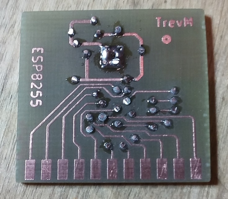
Bottom of my assembled VESC
Top of my assembled VESC
Ok, so I built it the best I could. Spent a couple of weeks dithering after that. Needed to pick up courage to power it up. But I did. It didn't go bang, it did smoke, but so little that it took me some time to track it down. See bottom picture, top left component is a diode, protection of 5V rail, it was smoking. I took it off, checked pads, 9 Volts instead of 5V!!!
See IC in middle of Top photo, that's the DRV8032, it converts supply to 5V. It has a heat sink pad in the middle underneath, I saw that, so carefully added a layer of heat sink compound, this was wrong, it needed to be soldered! But the 3V3 rail was intact!
So, I connected it up to PC and ST-Link could see it and program the processor. But nothing after that.
I protected surrounding components with Kapton tape, used hot air gun, lifted DRV chip off, cleaned it up, soldered it back on using hot air gun. Result, now got 5V, took off Kapton tape. Still seen by PC, still programs, but then nothing, blue LED is on, but it's directly wired to supply, no red of orange LEDs. So I re-flowed the processor using hot air gun.
Singed some of the connectors, now it's not seen by PC, probably fried the processor.
Next step: protect surrounding components with Kapton tape, use hot air gun to lift off processor. Thoroughly check all processor pads are connected as needed. Solder on new processor. But I'm in silly mode again, Need to snap out of it and buckle down.
11/12/2017
Interesting day, did 'Next Step' above, could find nothing wrong, fitted fresh processor.
Still no joy.
Used ST Cube MX and Keil to create a very simple firmware that simply lit Green and red LEDs, debug on and using internal oscillator. No LEDs.
Replaced both LEDS, now work! No idea why they weren't working.
Altered test firmware to alternately flash LEDs every 500 mS, ran it, both LEDS flashing.
Altered firmware to use 8MHz crystal, built, flashed, ran, LEDS still flashing, so crystal circuit ok.
Put in standard firmware again, ran up BLDC_Tool, still shows firmware is tool old. Firmware tab shows it supports 2.17 or 2.18.
But I saw in conf_general.h that I'm actually building and flashing 3.32!!!!
Smelt a rat, used git tools, vedder has updated the firmware for V6.00 (since being recruited by company that copyrighted VESC).
Created branch at 2.18, built and programmed that, finally I have working BLDC_Tool!!!!
No such thing as xml files for motors, going to have to play this by ear too.
Time to solder on motor wires and attach motor......
12/12/2017
Did that, told it to discover motor, spun up motor for about a second, then big bang!
Blown 10 mm wide track between right 2 FETs.
FETs removed
Track repaired.
This time I've tinned bottom of FETs and used heat gun to bed them down.
13/12/2017
It started working again, started to spin up, then bang.
1 FET split in half, another was cracked, now constantly shows DRV fault, so that's probably trashed.
I'm going to remove all 6 FETs and DRV chip, check all ancillary components, check all FETs out of circuit, then put it all back together and pray.
14/12/2017
Checking FETs was frustrating, lots of places on-line where they tell you that you need a lot of complex equipment to test them properly, then lots of other places where they show you how easy it is to test using a meter in diode mode. Well it doesn't work with my meter in diode mode! But none are cracked, none have shorts and 1 place on-line goes through lots of ways to test them, then at very end says that they are very robust, if the don't look damaged and they have no shorts then they are usually ok! Be nice if that was the 1st link I found and be nice if he put that bit first!
Soldered on new DRV chip with hot air, powered up, no more flashing red LED, just constant green, nice.
Soldered back on the 6 FETs, powered up, still constant green, nice.
Back to BDLC_Tool, run wizard, fails to complete!
There are 3 modes for motor: BLDC, FOC or DC! None of this means anything to me and the software isn't telling!
DC = Direct Current (like a battery), not AC (alternating current, like mains)
ESC = Electronic Speed Controller. This is a standard acronym in the world of Radio Control.
BLDC = BrushLess DC Motor. This is a standard acronym in the world of Radio Control.
FOC = Field Oriented Control. This is a not so standard acronym in the world of Radio Control.
"Simple off-the-shelf ESCs use basic back EMF to control multi-phase motors. Field Oriented Control (FOC) is a sensor-less form of commutation that can be integrated into any UAV" - Sounds good, doesn't really explain it for me!
"Every single motor is unique and the VESC needs to know certain parameters to run the motor. The VESC needs to know the motor resistance, electrical inductance and flux linkage (λ). From these basic values other values can be calculated that are essential for the motor operation."
But there is a wizard, Step 1 = press the RL button to measure the Resistance and Inductance of my motor! Nice, except it's not!
It's not repeatable, but does come up with some values, for my motor it says:
R: 13210.19 mOhms L: 23.11 uH
The manufacturers web page says the internal resistance of the motor is 0.021 Ohm, which I figure is 21 milli Ohms, sometimes the software comes up with 21000 mOhms, maybe mOhms means micro Ohms, but it's not telling, no idea if 23.11 uH is correct.
Step 2 = measure λ.
It wants 3 values: I, D, ω
- I is in Amps, it's current, but minimum current, maximum current, who knows, it's not telling.
- D = Duty Cycle, so it's a value between 0 and 1, with 0.5 being middle, but it's not telling how to calculate or figure out what that is.
- ω is in ERPM, no idea at all! ERPM appears to be Electrical Revolutions Per Minute. This appears to be VESC specific! "Erpm = (Mech.rpm) x (number of pole pair (magnets) of the motor)".
Manufacturer doesn't advertise how many poles or magnets my motor has, but a search finds it has 14 poles.
Tried lots of different values in BDLC and FOC modes, got it so it spins up the motor and completes.
But there appears to be no way to test it, there is a little icon that allows control using keyboard arrow keys, but there are 4 keys and they aren't letting on what each means and it doesn't seem to do anything except make my motor do some weird sounds.
So, I went to App, wired up the accelerator, looks good in tool.
Does naff all with my motor!
All very frustrating and annoying.
At least with old system, I have full source, that I know.
So, I went back to old system, put in old firmware using ST Link, ran up old tool.
This actually explains some of the terminology better!
So, I'm basically sitting looking at it, deciding what values to use, it doesn't run unless attached to powered up PCB, so it's powered up attached to battery and motor, but should be doing nothing.
Then the PCB goes BANG! Blown a hole in the DRV chip!
This was 10:30, ordered some more DRV chips.
You ever get into a situation like this?
£350 spent, weeks getting to this point, not working. Too far in the quit?
I'm thinking "don't throw good money after bad", I'm thinking put the PCB on a nice solid floor and smash it with a club hammer.
I really do wish I'd never started this, but I'm just too obstinate to quit.
15/12/2017
Farnell order was out for delivery at 06:00 this morning.
Spent all day researching motor, battery, going through firmware code.
Whilst sitting here, UPS reports they tried and failed to delivery twice, blatant lie, I have full video surveillance and their was no 'not delivered' cards. Phoned UPS, if lucky I might get replacement DEVs tomorrow, also ordered some from RS for delivery Monday.
This is all a bit annoying.
Got some feedback on Forum, the DEV chip may have been half working previously, that made discovery fail, dying to give it another go.
19/12/2017
Took off DRV chip, lots of damage, blown off pad under lowest right pin. Fixed that, fitted new chip, attached to PSU, nothing, another big supply pad had blown, fixed that, PSU short.
Gave up, now building a 2nd VESC using new PCB, very carefully soldering on every component and fully checking each is soldered correctly. Had a few shortages, ordered from RS. Should be here tomorrow.
24/12/2017
Powered up the new VESC very carefully on PSU, nothing worked, was fine until I started trying to detect motor, then 3 red flashes, DRV8302 fault every time. Replaced DRV8302 and finally it is fully working.
10/12/2017 to 24/12/2017 = 2 weeks, was already practiced on drag soldering, can now do heat gun soldering. 1 scrapped VESC and parts.
This has been the hardest electronics I've ever built.
All I've now got to do is to fit it to the bike, how hard can that be?
27/12/2017
Been a bit busy with other things last couple of days :-)
This must be an electric assisted bike, it must fully function the same as it used to except when assistance needed, then it must behave like an ebike.
My Dad got a special wheel made up:
Standard gears in standard arrangement attached to standard side, but on this side it has a Sturmey Archer freewheel screwed on. The idea being that the motor freewheels whilst the bike is in standard use, but motor turns wheel in ebike mode, I need to attach the pulley to the freewheel.
Sounds good, but it can't work, using standard Sturmey Archer freewheel, it operates the other way, be fine if we want the bike to go backwards in eBike mode!
Many thanks to zigzag for his post here:
Based upon this, I'm going to hack it and reverse it!
Sprocket itself is easy, just turn it over (re-assemble upside down) :-)
Problem is the pawls, they can be reversed, but the pawl cutouts need modifying.
PCB drill with dremel type bits and a little later....
I made it the same depth after taking photo.
During re-assembly. Now fully working reversed, I still have concerns over fitting to wheel, it's left hand thread which means it tightens up in standard use, but I've reversed it, so now it will unscrew in standard use! Maybe locktight will do it, but I'm thinking I may need to add some locking rods through the threads, still thinking this through....
30/12/2017
Rear pulley done and fitted, hub is 2 piece to sandwich freewheel, spokes all printed separate, pulley ring printed in 4 segments, was the only way I could get all the weird angles. All dove tail joints, then all glued together with epoxy.
Pulley and drive band on bike.
Very happy with how true it is, nothing even close to rubbing, at least 2 mm clearance everywhere.
Locking the freewheel on the threads with a pin proved to be impossible, freewheel case must be hardened steel, I couldn't touch it, and even if I could, it's so thin that it would be severely weakened.
So, I've been a bit of a cowboy, Araldite 5 minute epoxy now on the threads. If it ever needs to get undone then I'm hoping a little heat will free it up.
Next challenge is to mount the motor on that very thin upright. Even worse than that, motor has to be mounted some way out or the drive band will rub the upright due to the angles.
1/1/2018
Motor mounted to bike, plugged it in, wife on throttle, works quite well, though of course off load. Had to hold her back, wife was going for full throttle! Yeah, motor bracket is red, I ran out of light grey, on order, will reprint once I get it. Control box to mount VESC to frame next, then I can adjust wire lengths and actually try it on the road, then just for completeness I'll make a box to hold and protect battery in saddle bag.
Testing on road will be a problem, I'm back at work tomorrow, next time I'm home with daylight is next week end.
2/1/2018
Designed and printed VESC case in red PLA. It fits nicely under mini-rack (saddle bad support). I adjusted the length of motor wires, added long thin wires from VESC battery terminals (to route to handlebar mounted power gauge), then waterproofed VESC electronics.
I roughly tie wrapped motor leads in place and roughly tie wrapped cables between VESC and handle bars. I roughly mounted accelerator in place on handlebars.
All wires will be wrapped in silver PVC tape and mounted to frame using same tape, so they should be mostly invisible. I connected battery inside saddlebag.
Ok, so it's fully functional. It will be mostly completed when I get the silver PVC tape, light gray PLA filament and battery gauge, all expected some time in the next 2 weeks.
But now was the moment of truth, get aboard and see how it moves slowly between hall and living room.
This is where it mostly went down hill :-(
Ok, face the truth, I'm a short arse, I can't actually get on the bike, my legs are too short!!!!! Even if I put the saddle down to lowest, I think I'd struggle!!!!
I did manage to sit uncomfortably on the cross bar, tried to go forward and it made a horrible noise. Got back off and examined, take off from static is a bit dodgy under load with VESC, that was the noise I heard. If I very slowly and carefully use accelerator, sometimes it's ok.
It may be ok for my Dad as he is much lighter than me.
But I'm now awaiting the post man for a while.
6/1/2018
Light Grey PLA and Silver PVC tape arrived, still awaiting Battery Gauge. Re-printed (but not fitted) VESC box, still need to re-print motor mount.
But this morning I lowered the seat and took it for a test drive. Felt good for a very short time (about 50 yards), then it didn't sound or feel right. Pushed it back home. Pulley at motor had come loose, has 2 grub screws, 1 now gone. It was too loose to work, but too tight to take off, it had worked it's way up the motor shaft causing belt to come free.
One of the few parts I haven't made and thought would be ok! Is that good news or bad news?
The grub screw mountings (1 screw missing)
So, I've modified:
I've ground a flat in the shaft where the remaining grub screw hits.
I've ground a groove in the shaft, I then tried to drill a hole between pulley and shaft to make a key way into which I planned to put a piece of rod. This didn't work, drill snapped off. But this could be a good thing, the drill acts as a hardened steel key stuck in place on the pulley. This could work.
I've ordered some more pulleys, they are very low cost, I'm considering ordering a new motor shaft, maybe I could weld them together some how. Pulleys are aluminium, shaft is hardened steel.